%20(4%20Inch%20(100%20mm))?unique=ac78e10)


%20(4%20Inch%20(100%20mm))?unique=ac78e10)


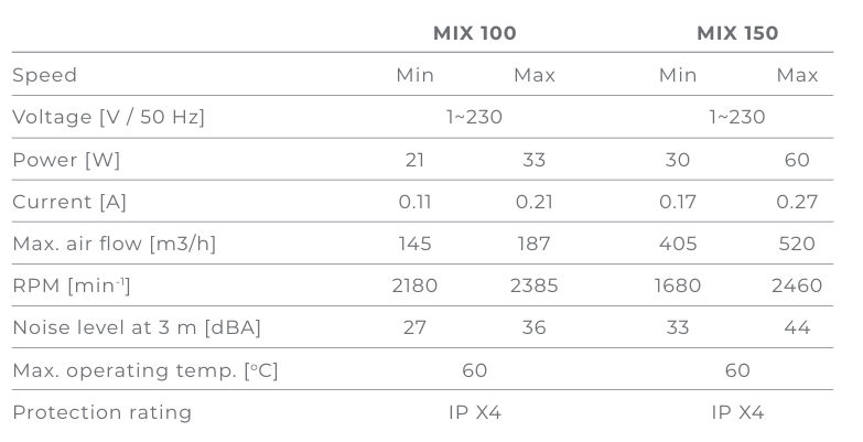
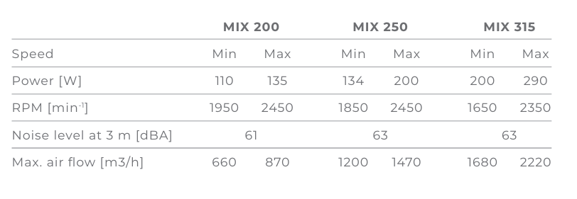
MIX 100-315 (Mixed Flow Fans)
DWELL MIX 100–315 Inline Duct Fan – High-Performance Ventilation for Modern Spaces
- Combines the power of centrifugal fans with the efficiency of axial flow for strong, steady performance
- Delivers high air pressure and low noise, perfect for demanding home or commercial ventilation setups
- Compatible with Ø100 to Ø315 mm round ducts, ideal for flexible installation in various duct systems
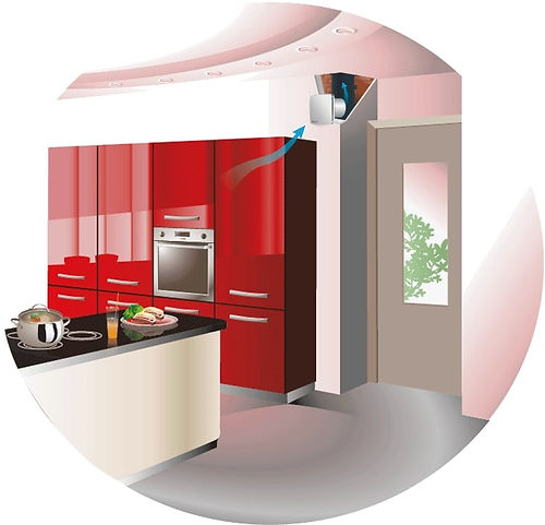
- Designed for kitchens, bathrooms, laundries, and other humid spaces
- Also suitable for flats, shops, cafes, and cottages needing continuous, energy-efficient air circulation
- Advanced motor design ensures long life and quiet operation, even under extended use
- Perfect for areas where space-saving and powerful air movement is essential
💡 One of the most popular inline fans online, trusted globally for its reliability, performance, and durability.

Application
1. Dwell Mix100 fans are featured with wide capabilities and high performance of axial and centrifugal fans and are specifically designed for supply and exhaust ventilation of premises requiring high pressure, powerful air flow and low noise level.
2. The fans are compatible with round air ducts from Ø 100 to 315 mm. Exhaust ventilation systems based on the Dwell Mix100 fans are the best solution for ventilation of bathrooms and kitchens and other humid premises as well for ventilation of flats, cottages, shops, cafes, etc.
Design
1. The casing is made of high-quality durable plastic.
2. All the models may be equipped with a regulated timer with turn-off delay adjustable from 2 to 30 min.
3. The removable impeller and motor block with a terminal box is fixed to the casing assembled with the spigots by means of special clamps with latches. This makes the fan maintenance fast and easy. The fan maintenance does not require total disassembling. Just pull out the central block from the casing and perform required servicing.
Mounting
1. The fans are suitable for mounting at any angle and point of the system. Several fans may be installed inside one system.
2. Several fans may be installed inside one system:
a. parallel mounting to increase air flow;
b. in series mounting to increase operating pressure;
3. The fan case is equipped with a flat mounting plate to attach the fan to the wall.
4. The mounting box may be installed in any position to facilitate mounting and wiring.
Motor
1. The models of Mixed Flow series are equipped with a single phase motor and are available in single or two speed modifications. Some dimension types are available with a more powerful motor.
2. The motors have thermal overheating protection to prevent the motor overload.
3. The ball bearings extend the motor service life up to 40 000 hrs. at non-stop operation.
4. The motor has IP X4 ingress protection rating.
Speed Control
1. The double-speed motors are controlled with a built-in switch (V option) or an external switch for multi-speed fans (available upon separate order).
2. An integrated speed controller (option P), an external TRIAC or autotransformer speed controller (available upon separate order) are used for smooth speed control when connected to the maximum speed terminal.
Operational Logic
1. Set the desired air temperature (set point of the thermostat) with the thermostat control knob. Set the required minimum impeller speed (air flow) with the speed control knob. The motor switches to maximum speed (maximum air flow) as the temperature reaches and exceeds the set temperature set point. The motor switches to the pre-set speed as the temperature drops down below the set temperature point.
2. To avoid the frequent motor switching, e.g. when the temperature in the supply air duct is equal to the threshold value, the switching delay time is activated.
There are two switch delay patterns for various cases:
1. The temperature sensor-based switch delay (U option): the motor switches to higher speed as the air temperature exceeds 2°C above the set thermostat set point. The motor revers to the pre-set lower speed as the air temperature drops below the thermostat set point. This pattern is used to keep air temperature to within 2°C. In this case the fan switches are rare.
2. The timer-based switch delay (U1 option): as the air temperature exceeds the set thermostat set point, the motor switches to higher speed and the switch delay timer is activated for 5 min. The motor reverts to lower speed as the air temperature drops down below the thermostat set point and only after the timer countdown. This pattern is used for exact air temperature control. The fan changes its speed more often as compared to the temperature sensor-based switch delay, however the minimum timer interval is 5 minutes.


| Parameter | MIX 100 | MIX 150 |
|---|---|---|
| D | 96 | 146 |
| B | 167 | 223 |
| H | 190 | 250 |
| L | 246 | 295 |
| [KG] | 1.45 | 2.65 |

Application
1. Continuous or periodic exhaust ventilation of bathroom, showers, kitchens and other utility spaces.
2. Ventilation shaft mounting or duct connection.
3. Low to medium air flow motion for short distances at low air resistance.
4. Compatible with Ø 100-, 120-, 125- and 150-mm air ducts
Design
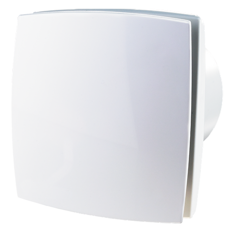
1. Modern design and aesthetic look.
2. The casing and the impeller are made of high-quality durable ABS plastic, UV resistant.
3. Various decorative plates for the front panel of the natural aluminum.
4. The intellectual impeller design makes the fan efficiency high and the service lifelong.
5. Protection rating IP34.
Mounting
1. The fan is mounted directly into the ventilation shaft.
2. In case of remote location of the ventilation shaft flexible air ducts may be used. The air duct is connected to the fan exhaust flange through a clamp.
3. Fixed to the wall by means of screws.
4. Suitable for ceiling mounting.
5. To connect a fan with a 12 V low voltage motor to 220 V/50 Hz power mains, it is necessary to purchase a step-down transformer (e.g. the TRF 220/12-25 transformer)
Motor
1. Reliable and low-watt electric motor.
2. Designed for continuous operation and requires no maintenance.
3. Equipped with overheating protection.
Speed Control
Manual:
1. The fan is controlled by a room light switch. It is not included in the delivery set.
2. The fan is controlled by the built-in pull cord switch V. Not applied in case of ceiling mounting.
3. Speed control is possible through a thyristor speed controller (see Electrical Accessories). Several fans may be connected to the same controller. Speed controllers can not be connected to the fans with Т, ТН, ТР, VТ, VТН modifications.
Automatic:
1. By the BU-1-60 electronic control unit. The control unit is supplied separately.
2. By the T timer (the built-in turn-off delay timer enables the fan operation within 2 to 30 minutes after the fan switching off).
3. By the humidity sensor and the TH timer (if the humidity level in the room exceeds the sensor threshold adjustable value within 60-90 % the fan switches automatically on and operates until the humidity level drops to the standard level, after that the fan continues operating within the time period according to the timer setting, then shuts down).
Parameter | Value |
Ø D | 100mm |
B | 152mm |
H | 120mm |
L | 126mm |
L1 | 130mm |
Application
1. Continuous or periodic exhaust ventilation of bathroom, showers, kitchens and other utility spaces.
2. Ventilation shaft mounting or duct connection.
3. Low to medium air flow motion for short distances at low air resistance.
4. Compatible with Ø 100-, 120-, 125- and 150-mm air ducts
Design
1. Modern design and aesthetic look.
2. The casing and the impeller are made of high-quality durable ABS plastic, UV resistant.
3. Various decorative plates for the front panel of the natural aluminum.
4. The intellectual impeller design makes the fan efficiency high and the service lifelong.
5. Protection rating IP34.
Mounting
1. The fan is mounted directly into the ventilation shaft.
2. In case of remote location of the ventilation shaft flexible air ducts may be used. The air duct is connected to the fan exhaust flange through a clamp.
3. Fixed to the wall by means of screws.
4. Suitable for ceiling mounting.
5. To connect a fan with a 12 V low voltage motor to 220 V/50 Hz power mains, it is necessary to purchase a step-down transformer (e.g. the TRF 220/12-25 transformer)
Motor
1. Reliable and low-watt electric motor.
2. Designed for continuous operation and requires no maintenance.
3. Equipped with overheating protection.
Speed Control
Manual:
1. The fan is controlled by a room light switch. It is not included in the delivery set.
2. The fan is controlled by the built-in pull cord switch V. Not applied in case of ceiling mounting.
3. Speed control is possible through a thyristor speed controller (see Electrical Accessories). Several fans may be connected to the same controller. Speed controllers can not be connected to the fans with Т, ТН, ТР, VТ, VТН modifications.
Automatic:
1. By the BU-1-60 electronic control unit. The control unit is supplied separately.
2. By the T timer (the built-in turn-off delay timer enables the fan operation within 2 to 30 minutes after the fan switching off).
3. By the humidity sensor and the TH timer (if the humidity level in the room exceeds the sensor threshold adjustable value within 60-90 % the fan switches automatically on and operates until the humidity level drops to the standard level, after that the fan continues operating within the time period according to the timer setting, then shuts down).